
TMR Angle Sensors
Selection Guide
Please view our selection guide for further information about our products:
TMR Sensor Selection Guide
View online: Selection Guide for TMR sensors
Download PDF: Selection Guide for TMR sensors
TMR Sensors
The TMR sensors of TDK are a new type of magnetic sensors utilizing a TMR element, which is a highly-sensitive reproducing element of an HDD head.
The reading elements of HDD heads are based on the magnetoresistance effect, which refers to a change in resistance induced by the application of an external magnetic field. Since the 1980's, they have promoted significant improvement of the recording density of HDDs, while evolving into AMR (anisotropic magnetoresistance effect) elements, GMR (giant magnetoresistance effect) elements, and TMR (tunnel magnetoresistance effect) elements. The basic structure of each element is shown in Fig. 1.
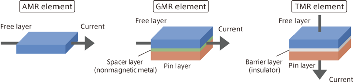
Fig. 1 Structures of AMR, GMR, and TMR elements (schematic diagrams)
The magnetic structure of a TMR element is almost the same as that of a GMR element. However, in a TMR element, the current flows perpendicular to the film surface, while it flows horizontally to the film surface in a GMR element.
A TMR element is a thin-film element with a structure in which a barrier layer made of a thin insulator of 1 to 2nm is sandwiched between two ferromagnetic layers (free layer/pin layer), made using advanced thin-film processing technology. Although the magnetization direction of the pin layer is fixed, the magnetization direction of the free layer changes according to the external magnetic field direction. The electrical resistance of the TMR element changes along with this change in the free layer. The electrical resistance becomes the smallest when the magnetization directions of the pin layer and free layer are parallel, causing a large current to flow into the barrier layer. When the magnetization directions are antiparallel, the resistance becomes extremely large, and almost no current flows into the barrier layer (Fig. 2).

Fig. 2 Principle of TMR
Left: when the magnetization directions of the free layer and pin layer are parallel, the resistance becomes small and a large current flows.
Right: when the magnetization directions of the free layer and pin layer are antiparallel, the resistance becomes large and only a weak current flows.
The output of a TMR sensor is 20 times higher than that of an AMR sensor, and 6 times higher than that of a GMR sensor
The rate of change in the resistance of an element is expressed by a value called the MR ratio. The MR ratios of conventional AMR elements and GMR elements are about 3% and 12% respectively. In contrast, the MR ratio of a TMR element is 100%. In a GMR element, in which a non-magnetic Metal (Cu, etc.) is sandwiched between two ferromagnetic layers, electron transfer occurs as electric conduction in the metal. In a TMR element, on the other hand, electron transfer occurs as a quantum mechanical tunnel effect. For this reason, when the pin layer and free layer are in an antiparallel, a TMR element has an extreme characteristic in which electrons "cannot move almost at all," when compared to the characteristics of a GMR in which "it is hard for electrons to move." This causes a TMR element to exhibit an extremely large MR ratio, in addition to giving a distinctive character to its output, such as "Yes or no" or "1 or 0."
Moreover, this is also the reason why TMR elements are utilized as highly-sensitive reading element in HDDs today. Therefore, by using these highly-sensitive TMR elements as magnetic sensors, extremely large output can be obtained. In fact, the outputs of TDK TMR sensors reach 3,000 mV, which is 20 times larger than those of AMR sensors and 6 times larger than those of GMR sensors. Fig. 3 is a comparison of the characteristics of magnetic sensors using an AMR element, GMR element, and TMR element (when a voltage of 5 V is applied).


Fig. 3 Comparison of the characteristics of magnetic sensors using an AMR element, GMR element, and TMR element
Optimal for automotive electronic components or industrial equipment, with low temperature drift and aging deterioration
When a magnet is rotated on a TMR sensor, the magnetization direction of the free layer follows the magnetic field direction of the magnet, and the resistance of the element changes continuously. Since the resistance value is proportional to the relative angle between the magnetization directions of the pin layer and free layer, it can be utilized as an angle sensor (Fig. 4).
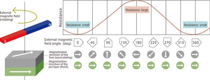
Fig. 4 Principle of angle sensor using TMR element
The magnetization direction of the pin layer is fixed, while the magnetization direction of the free layer follows the external magnetic field direction.
Since the resistance value of the element is proportional to the relative angle between the magnetization directions of the pin layer and free layer, it can perform 360° angle detection as an angle sensor.
The output of TDK TMR sensors is 500 times higher than that of a hall element, and also has low power consumption (5mW/under recommended conditions), which makes them ideal as sensors for automotive applications. For example, they can replace conventional angle sensors using hall elements, as automotive steering angle sensors or EPS (electric power steering) motor angle sensors.
A low temperature drift (changes in output caused by ambient temperature changes) is a basic requirement for sensors. Fig. 5 is a graph comparing the temperature dependence of the angle errors of TDK TMR sensor and a conventional AMR sensor. In the conventional AMR sensor, the angle error becomes extremely large on the low or high temperature side. By contrast, TDK TMR sensor maintains a stable angle accuracy in a broad temperature range (angle error of ±0.6° or smaller in the magnetic field range of 20 to 80mT and the temperature range of -40 to 150°C). In addition, low aging deterioration is another notable feature of TDK TMR sensors. Due to this feature, they are expected to be utilized not only in automotive electronic equipment but in various industrial equipment.
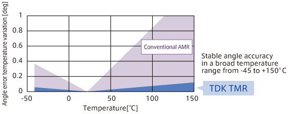
Fig. 5 Temperature dependence of the angle errors (comparison between TDK TMR sensor and a conventional AMR sensor)
Contributing to eco-driving as rotation sensors or current sensors in the future
Sensing technologies are greatly contributing to the improvement of the fuel efficiency of automobiles. In an automotive engine, crank angle sensors or cam angle sensors are used to obtain information for calculating the optimal timing and amount of fuel injection in the engine ECU (electronic control unit).
Although there are various types of crank angle or cam angle sensors, non-contact type magnetic sensors have become the mainstream because of their insusceptibility to wear or dust. A toothed gear pulsar (pulsar rotor) made of a magnetic material is attached to a crankshaft or cam shaft, and a magnetic sensor to which a magnetic field applied by a bias magnet is contactlessly placed to face it. When the engine starts and the gear pulsar rotates, the density of the magnetic flux from the magnet changes alternately due to the projections and recesses of the gear teeth. The magnetic sensor extracts this as a pulse signal, and detects the rotation speed based on the number of pulses per unit time. Because of this mechanism, these sensors are also called gear tooth sensors.
Compared to sensors using a hall element, TDK TMR sensors feature extremely high sensitivity and high output, and realize superior sensing capability as wheel velocity sensors for ABS (anti-lock braking) systems. Moreover, they can also be expected to be utilized as current sensors that conserve energy by controlling charging and discharging of batteries.
In recent years, demand for magnetic sensors has been increasing in fields such as automotive electronic equipment, industrial equipment, and consumer electronics. There is a mindset concerning sensors that, even if characteristics of the elements are somewhat inferior, these can be covered by how they are used (software).
However, a sensor is a type of transducer, and still requires good conversion efficiency. In addition, it is predicted that the detection accuracy required of automotive sensors will become approximately twice that of conventional sensors, in order to realize safer and more comfortable driving. TDK TMR sensors are innovative products featuring high output, high accuracy, as well as low temperature drift and low aging deterioration to meet severe and tough market requirement. Owing to these characteristics, they will be able to accommodate future strict accuracy requirements with ease. TDK is working on further expansion of the product lineup, so as to support a large variety of applications.