
Advanced Techniques in Motor Control
Electric motors have a pivotal role in various applications, transforming electrical energy into mechanical power. Efficient motor control is crucial, requiring the use of intelligent actuators or motor controllers. This article offers insights into the intricacies of DC motor control, specifically delving into Brushed DC (BDC), Brushless DC (BLDC), and Stepper motors.
Brushed DC Motors (BDC)
BDC motors, prevalent in industrial and automotive applications, rely on brushes for commutation. Comprising stator, rotor, brushes, and commutator, BDC motors offer simplicity and proportional speed and torque control. However, their lifespan is contingent on factors like load, currents, and vibrations.
The pitfall being the brushes which wear out over time and require maintenance. Furthermore, the commutator and brushes produce electric spikes which prohibits their utilization in applications where the working environment presents flammable gases or exhibits a fire hazard. Fig. 1 shows the BDC motor flux scheme in which the commutator and brushes mechanically manage the rotor flux direction to keep the rotor moving.
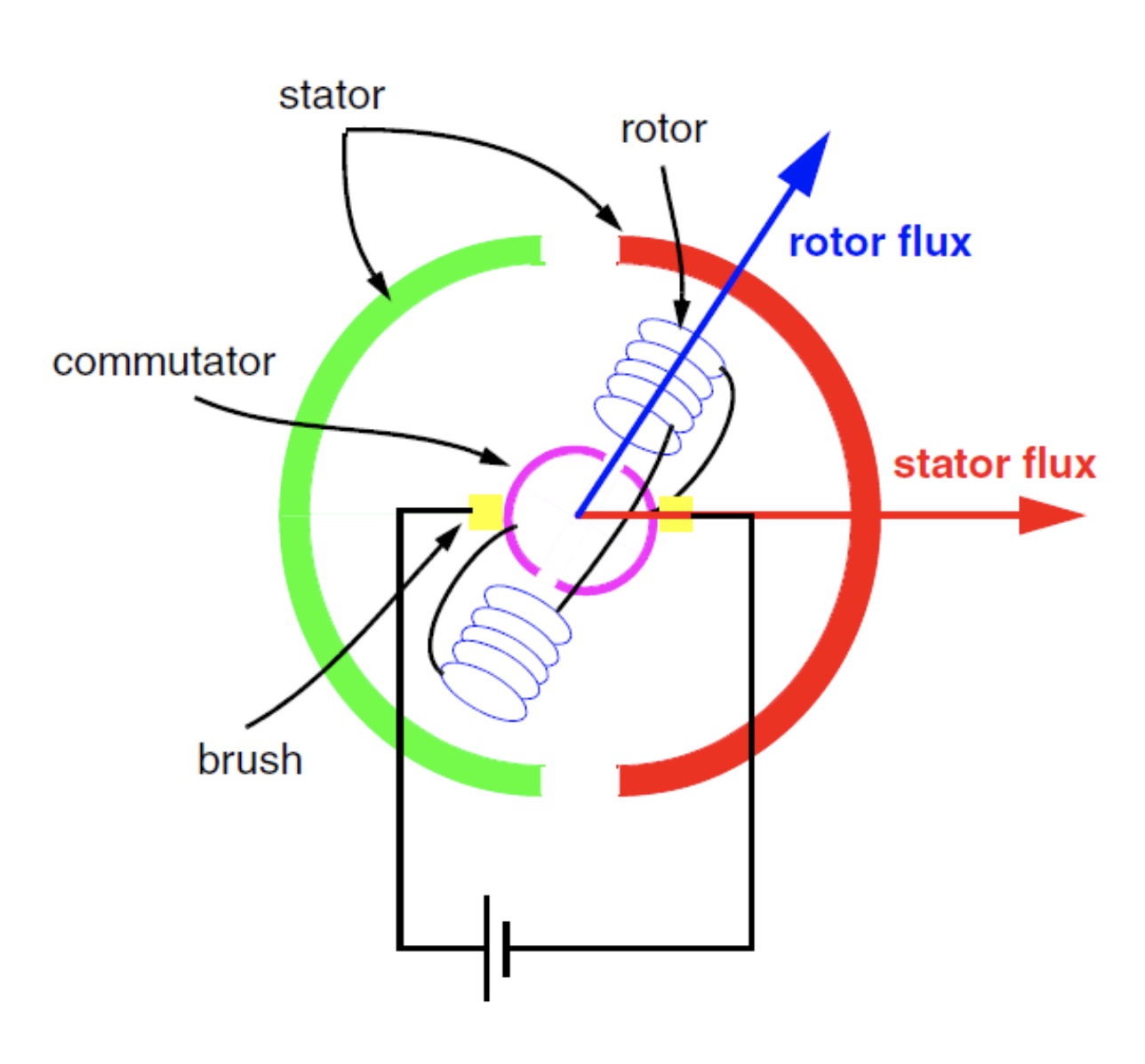
Fig. 1: BDC motor flux scheme.
Although prone to maintenance (or replacement) costs, the BDC motor has been for a long time the preferred solution in the Automotive market for small actuators because of its attractive cost and easy operation, but attention because the price argument is not anymore always true as there are many companies shifting to the BLDC motors.
For this kind of machines, in order to control the torque, it suffices to adjust the applied voltage. Therefore, the most fundamental form of control method is derived, called V/f. The method, which assumes a constant airgap flux, correlates motor speed and stator voltage linearly. Such kind of control could make use of the following modulation.
Pulse Width Modulation (PWM):
Motor torque is directly proportional to current, controlled by adjusting voltage through pulse width modulation (PWM). High side MOSFETs (p-channel) are LOW active, requiring LOW voltage for activation. Low side MOSFETs (n-channel) are HIGH active, needing HIGH voltage for activation. Synchronization of opposite MOSFETs with the same PWM profile requires inversion logic.
In an example, depicted in Fig. 2, motor phase B is activated negatively, and phase A positively with a 20% PWM duty cycle.
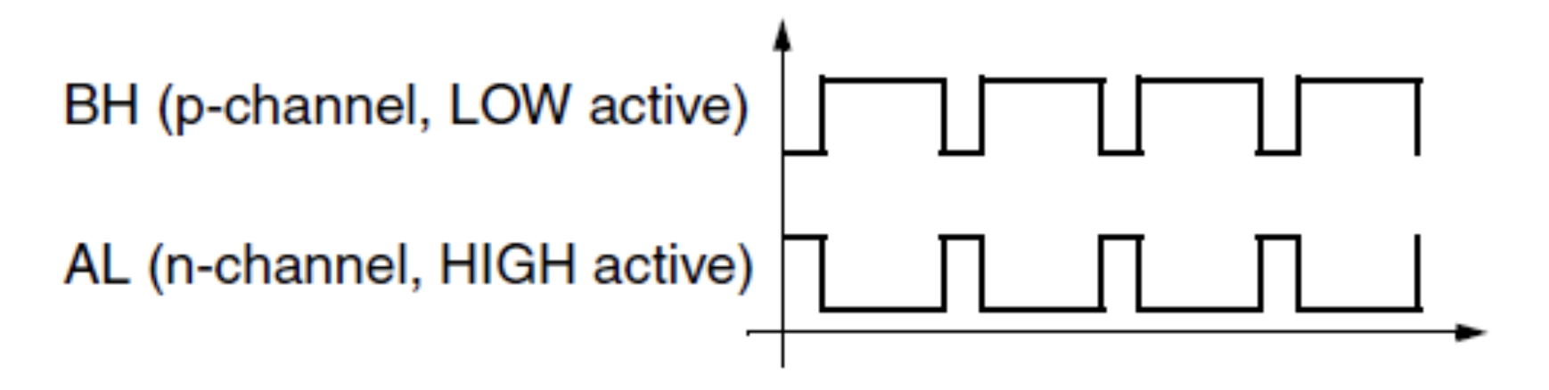
Fig 2: Output inversion logic during motor phases activation using a P/N-Channel half-bridge
An alternative method for energizing motor phases involves keeping one MOSFET active at 100% for the entire duration and applying a PWM profile only to the other MOSFET. This technique, illustrated in Fig. 3, can also be applied inversely, where AH is active at 100% and BL is controlled by a PWM signal.
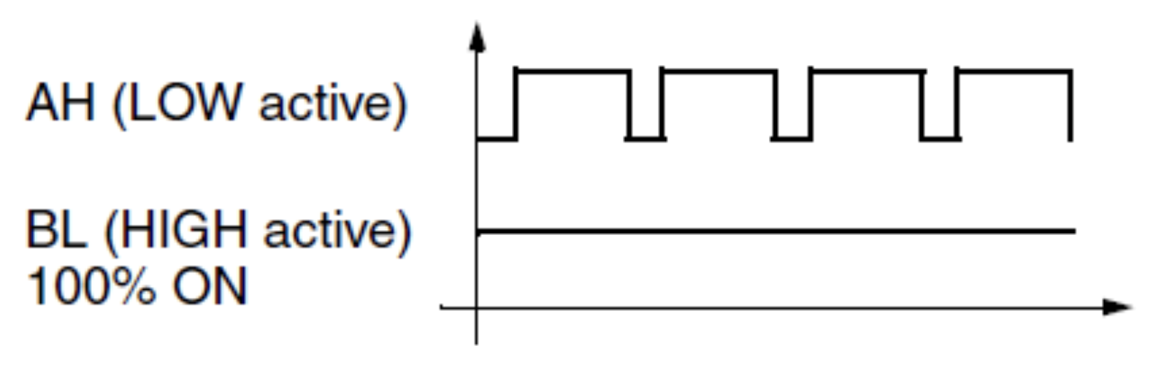
Fig. 3: Low side MOSFET active 100% of the time while the HS switch is the one responsible for the PWM regulation.
Brushless DC Motors (BLDC)
BLDC motors, electronically commutated and devoid of brushes, boast high reliability and efficiency. Magnets on the rotor, energized stator windings, and electronic commutation facilitate precise torque control. The absence of sliding contacts enhances motor lifespan, with ball bearings being the limiting factor.
As already mentioned, the electronic commutator is a must in this case, because the BLDC motor has no commutator and brushes. A stator flux shall be generated by an appropriate voltage vector in a way that the rotor flux produced by the magnets follow it, as shown in Fig. 4.
In this example, phase A is positively energized, phase B is negatively energized, and phase C is left open, causing the motor to rotate counterclockwise (assumed as the FORWARD direction). This leads to the explanation of the Six-Step commutation.
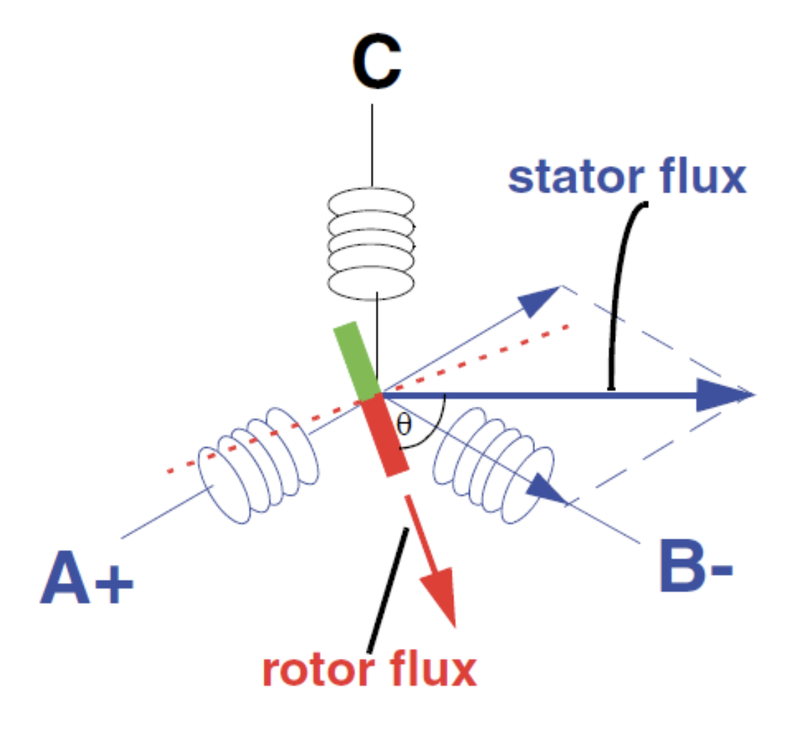
Fig. 4: Motor flux scheme, 3-phase BLDC motor
Six-Step Commutation:
The six-step commutation technique involves energizing two phases at a time while leaving a third phase floating (Hi-Z) in a three-phase motor. This modulation is usually deployed in conjunction with a BLDC motor, which is well-suited for this purpose. Due to the modulation characteristics of the Six-Step, it was found that modifying the Back Electromotive Force (BEMF) of a BLDC to a trapezoidal shape (instead of sinusoidal) would produce a more constant torque with less ripple (fluctuation).
Fig. 5 demonstrates the commutation vector diagram for the Six-Step modulation. Depending on which region of the hexagon the rotor flux position falls into, an appropriate voltage vector is picked. In this example, clockwise rotation is depicted. if sector 0 is selected, vector V4 will be applied. This causes a phase shift of 120° between rotor and stator flux. The vector length (amplitude) is controlled by the PWM’s duty cycle.
Knowing the rotor flux direction (rotor position) is crucial for optimal performance, and BLDC motors often use integrated sensors or external position sensors for this purpose. Special techniques, such as reading the BEMF, can also detect rotor position by means of the Zero-Crossings (ZC) without the need for sensors.
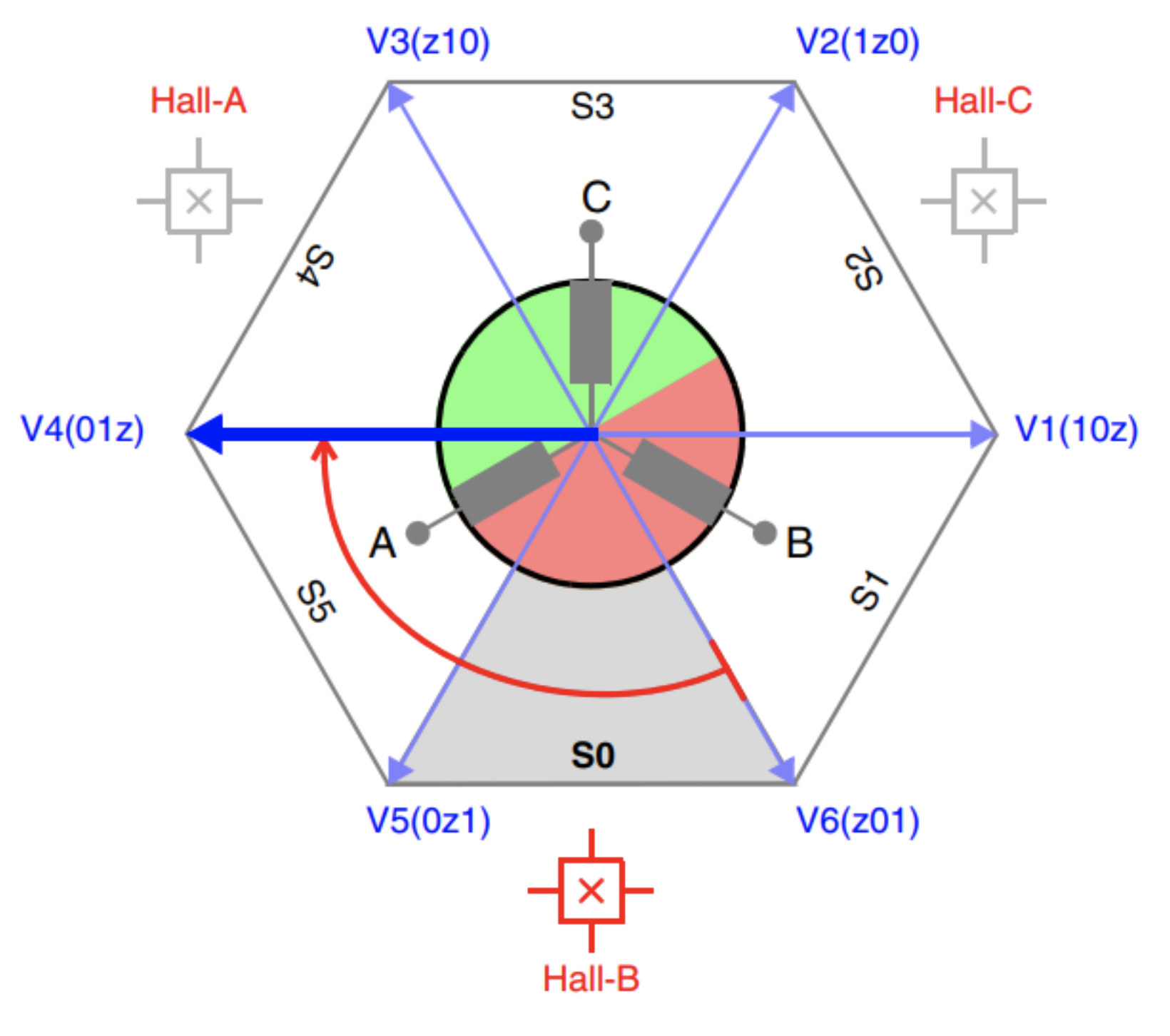
Fig. 5: Commutation vector diagram for the Six-Step modulation.
Sensorless Six-Step (ZC detection):
Thanks to the inherent characteristics of the Six-Step modulation, it is possible to sense the floating phase directly, allowing the controller to detect the ZC instants. This concept requires a motor with Y-connected stator windings for it to work. The common mode voltage is equivalent to the neutral point and is used as a reference for the comparator circuit which takes the floating phase as an input. Whenever a floating phase voltage crosses the virtual neutral voltage, a ZC is said to happen. Each sector has a predefined pattern for the correct Six-Step commutation sequence to take place. A single comparator is enough as long as the correct floating phase is multiplexed to it.
Fig. 6 depicts the CCW sequence and highlights the (ZC) instant for the transition within the sector 1. As an example, if a ZC of phase B is detected in sector 1, then the algorithm knows that 30 electrical degrees afterwards it should commutate the sector (electronic commutation), changing the applied voltage vector from “1z0” to “z10”.
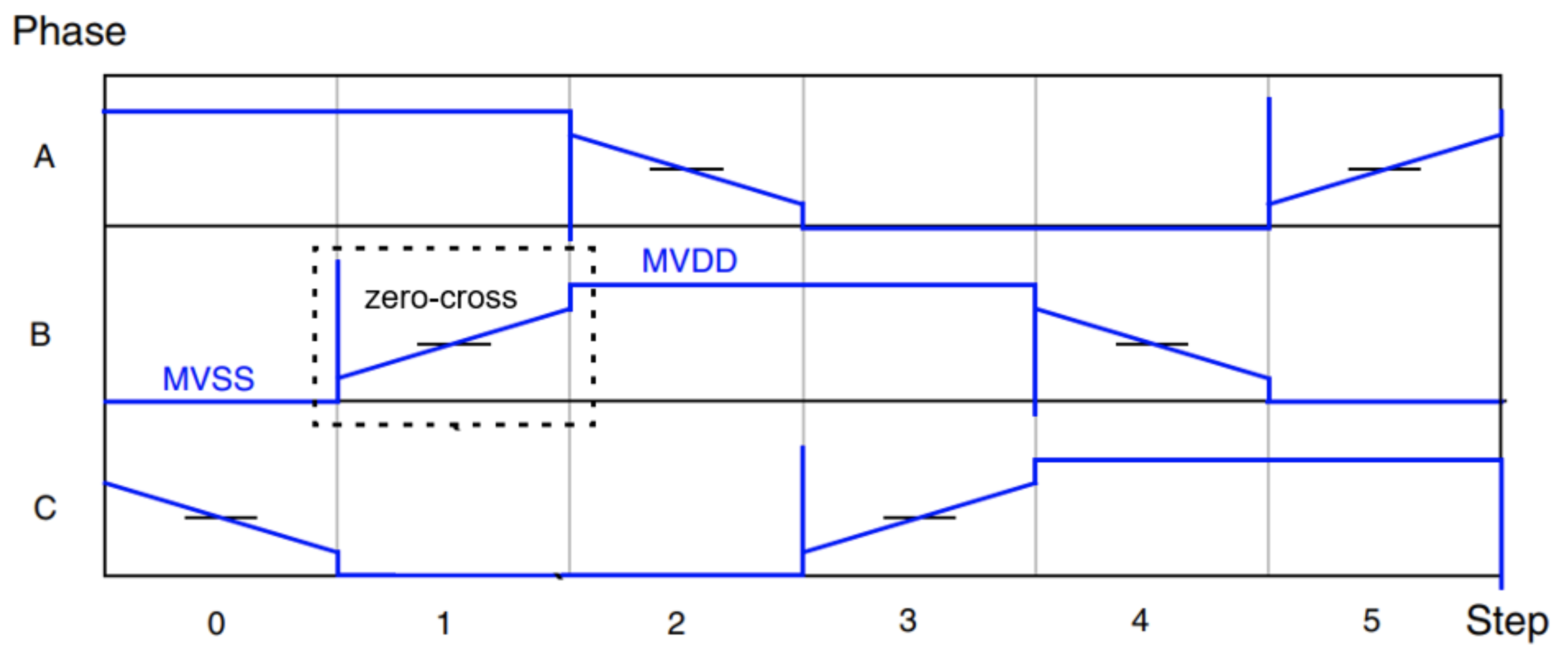
Fig. 6: Six-Step CCW commutation sequence.
Space Vector Modulation (SVM): Space Vector Modulation (SVM) is a technique used to generate sinusoidal shaped voltage with a three-phase voltage source inverter (VSI). SVM is typically used to drive AC induction motors, brushless DC motors (BLDC) and permanent magnet synchronous motor (PMSM). Fig. 7 shows an example for clockwise rotation. If sector 0 is entered with SVM also V4 will be applied. But this results in a phase shift of 90°.
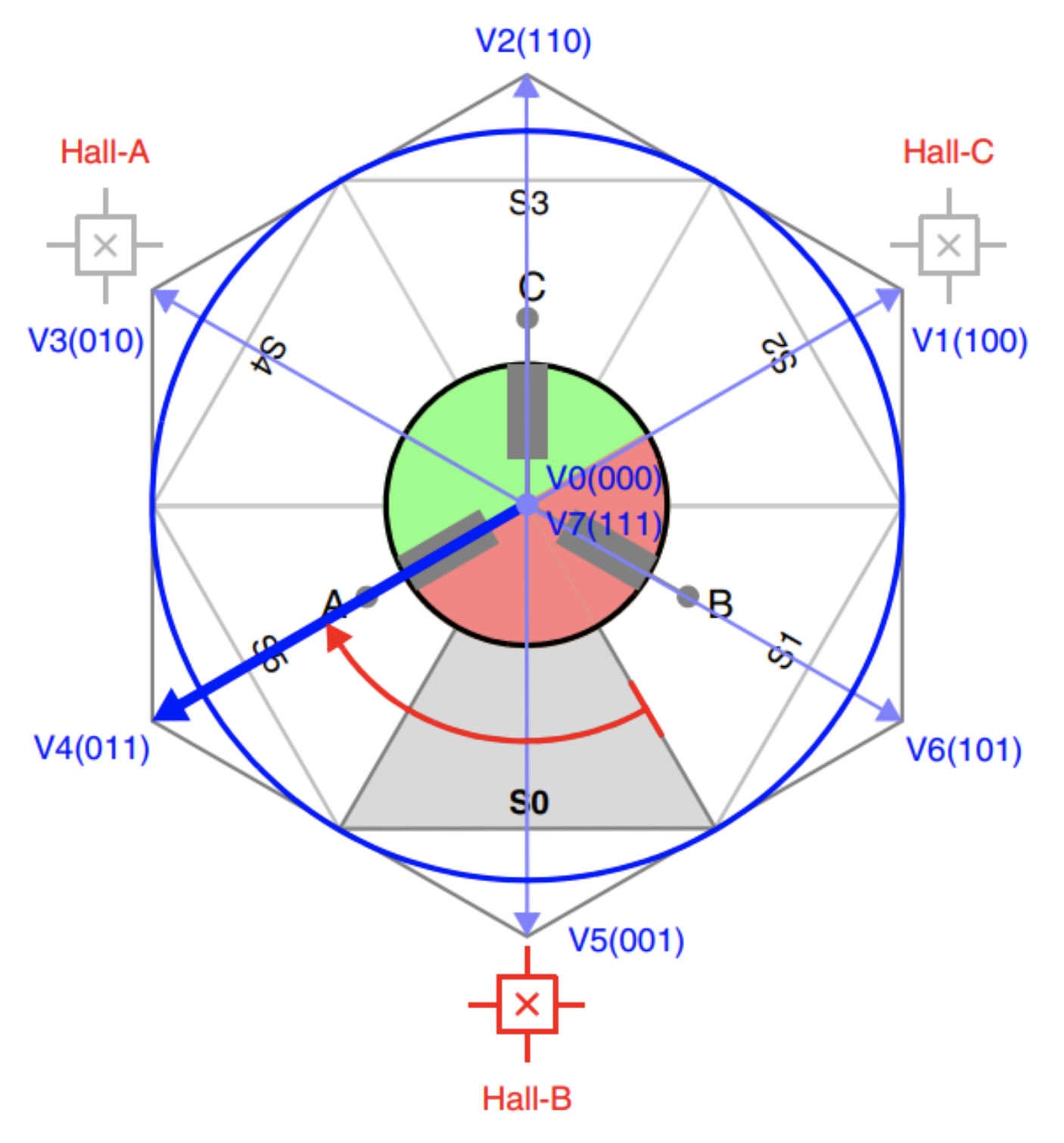
Fig. 7: Commutation vector diagram for the Space-Vector Modulation.
With Six-Step commutation the phase shift between stator and rotor field is maintained in 60°-steps only. Whereas, with SVM the two adjacent vectors are time multiplexed to create an intermediate (average) vector. By means of the intermediate vector, there is more granularity to synthesize the stator flux direction, thus making the SVM a more suited modulation algorithm to be used with advanced control schemes
Fig. 8 shows the construction of the intermediate vector. The direction of vector from Vx Fig. 7 can be adjusted by multiplexing the components Vk and Vk+1 of the two adjacent vectors. The absolute value (amplitude) of the vector is adjusted by the zero vector Vz (either “000” or “111”), which does not contribute to the direction. The shorter the dwell time tz' , the higher the vector amplitude. Anywhere in the hexagon, the intermediate vector can be referenced back to the first sector by the term (n - 1) · π/3
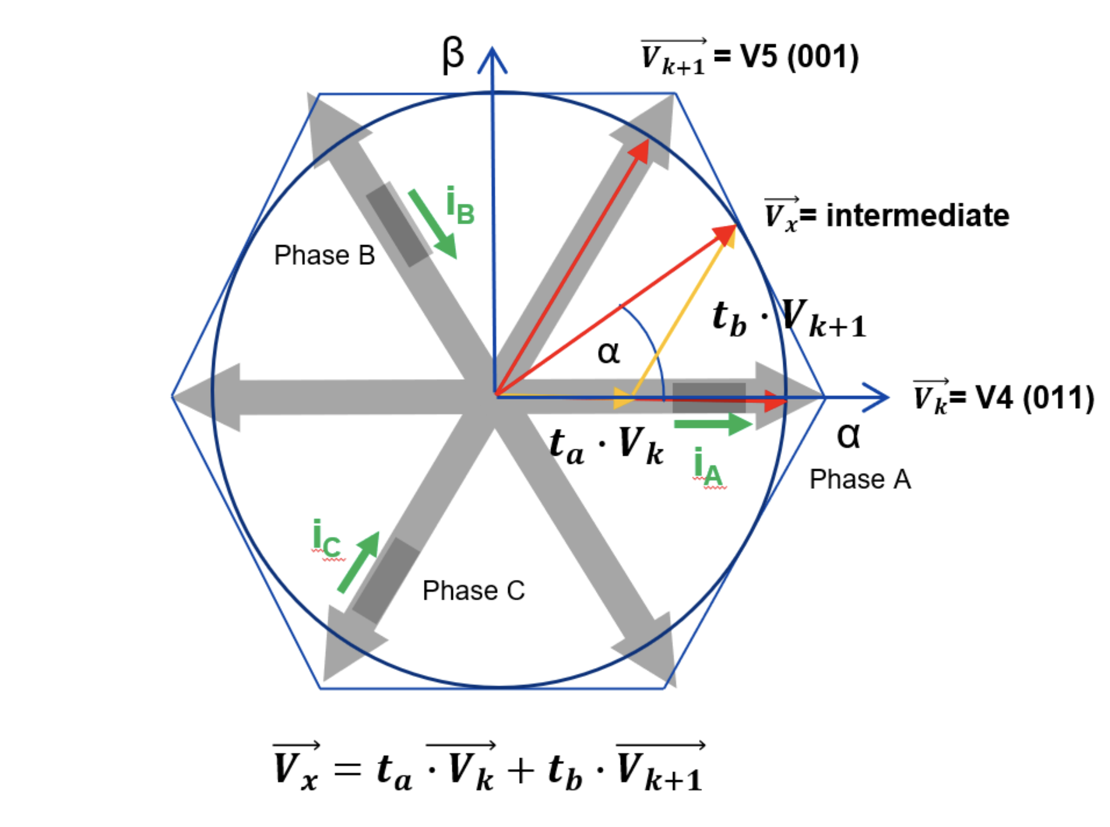
Fig. 8: SVM construction of the intermediate vector from sector S5 (V4) to S0 (V5).
The following equations can be used to calculate the dwell time from the voltage vector projections on the real and imaginary axes times are the following (valid for ![]() ):
):
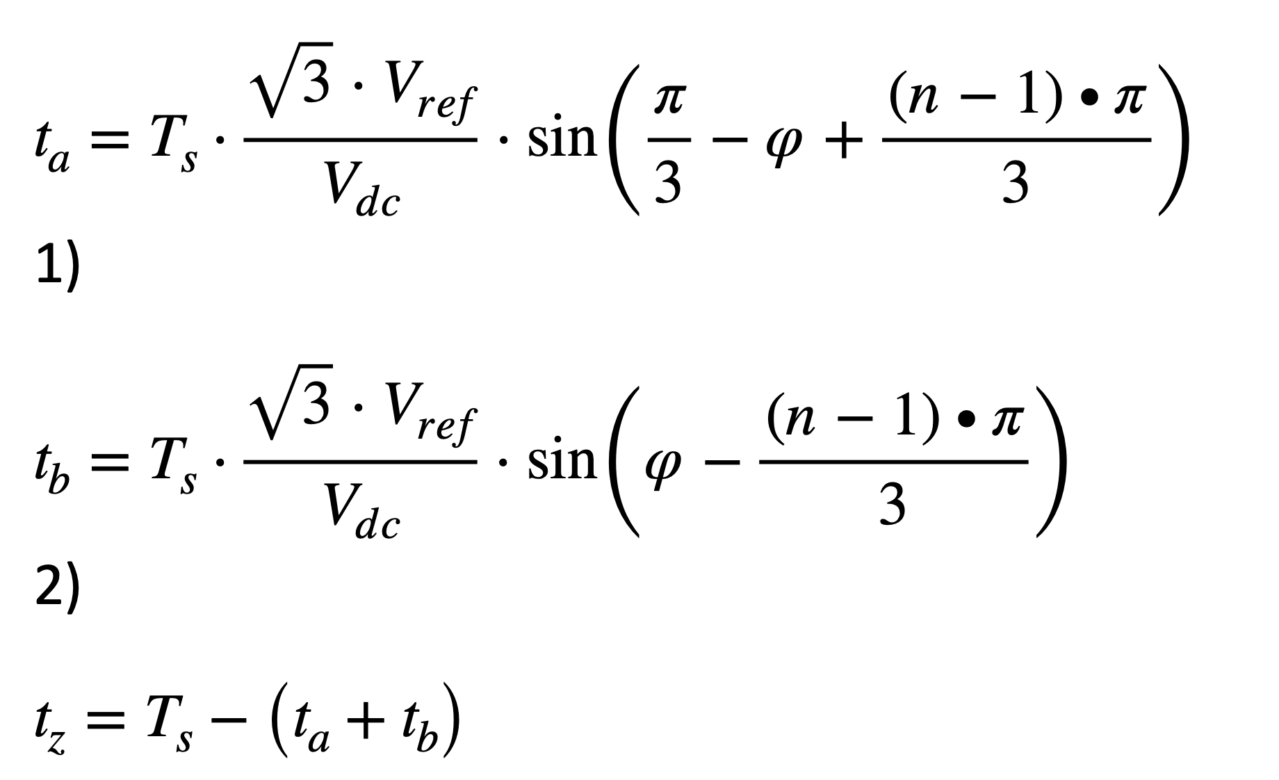
(Eq. 1) (Eq. 2) (Eq. 3)
Field Oriented Control (FOC):
The Field Oriented Control (FOC) can be understood as the instantaneous regulation of the torque of the electric machine. The instantaneous torque equation is a function of the flux linkage vector and the stator current vector.
The procedure is based on the reference frame theory and enables the designer to breakdown the complex three-phase system into an equivalent model in the dq system tied to the rotor synchronous frame. As a result, instead of having to manipulate the three-phase quantities (currents and voltages), the algorithm has to control two DC terms, one related to the torque (q-axis) and another one related to the flux (d-axis).
Fig. 9 represents the transformations and change of system references. The explanation about the transformations Clarke, Park and all the mathematical manipulation is out of the scope of this document. The αβ axes are orthogonal to each other and fixed to same position. On the other hand, the dq axes are rotating with the synchronous speed. The rotor flux position lines up with the d-axis.
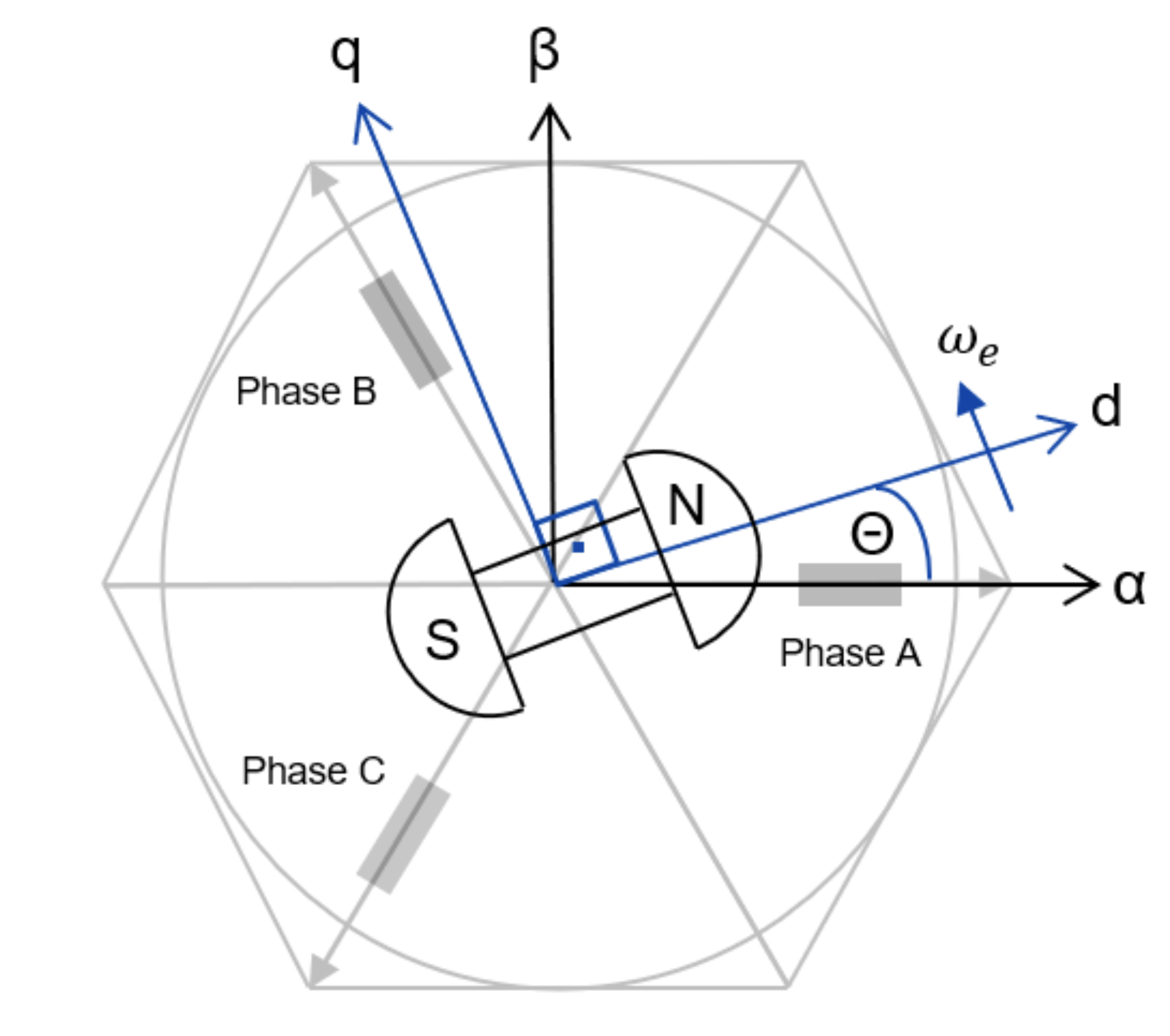
Fig. 9: Reference frame theory applied to the BLDC machine.
Fig. 10-a depicts the block diagram for the FOC speed control loop (q-axis) while Fig. 10-b shows the flux regulator (d-axis) part. The output of the speed controller is said to be the q-axis reference current which in turns feed the inner current regulator that generates a q-axis reference voltage. Due to the cross-coupling term between the q- and d-axes, there is a need to take them into account in the regulator loop. There are several ways to compensate for them, either use of a feed-forward scheme to cancel the term or a cascade regulator design whose fastest loop is the d-axis regulator.
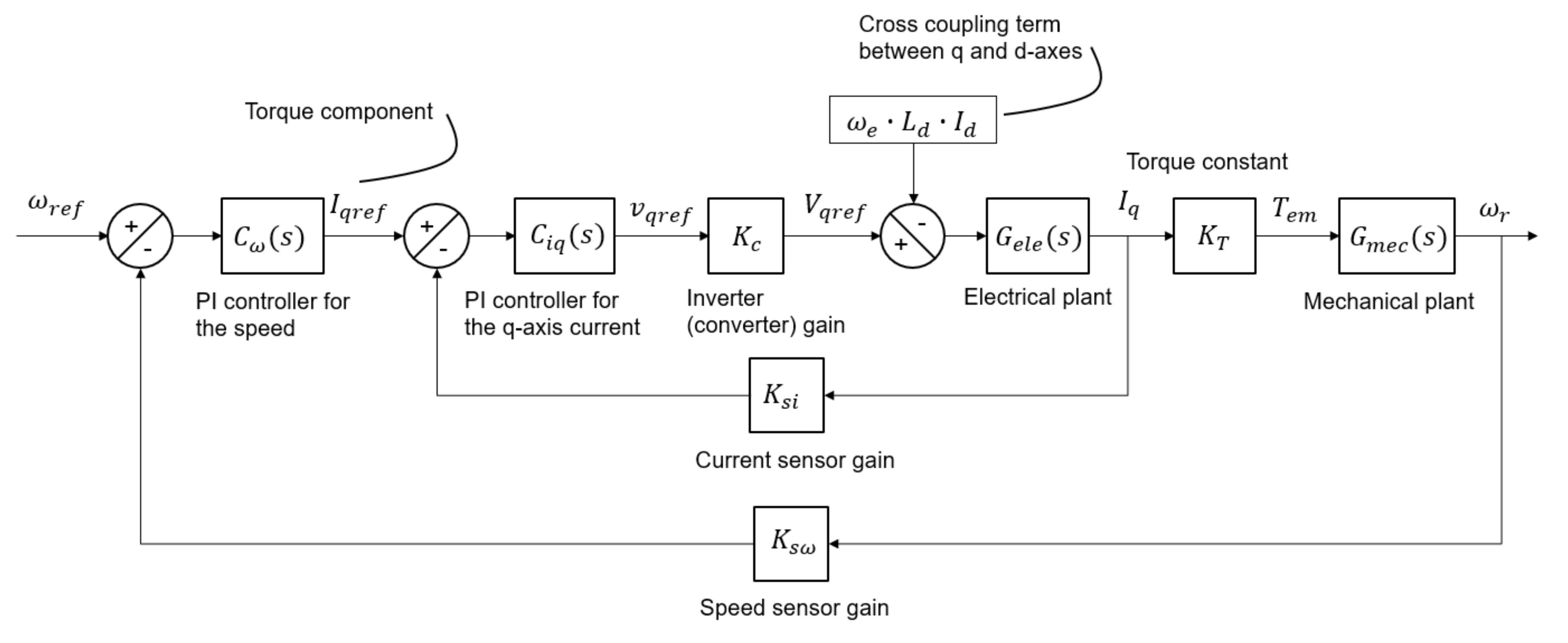
Speed and torque regulator (q-axis).
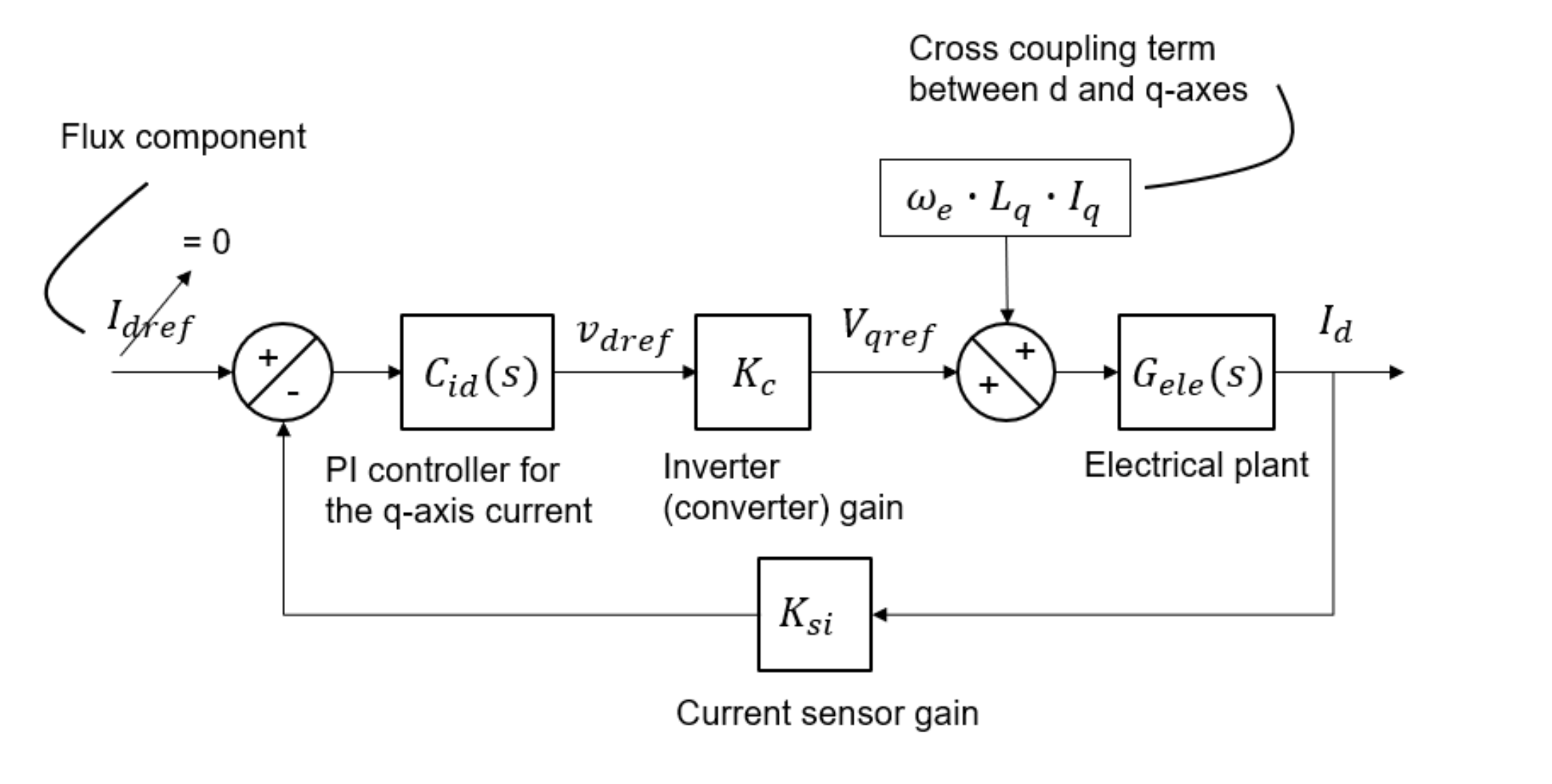
Flux regulator (d-axis).
Fig. 10: FOC block diagrams for both axes.
Maximum Torque Per Ampere (MPTA) and Field Weakening (FW):
The Maximum Torque Per Ampere (MPTA) is a technique to minimize the copper losses in the machine and it is applied to the already laid out FOC regulator scheme. The phasor diagram of Fig. 11-a demonstrates this concept. In this operation mode, the stator current vector and the rotor magnetic field are kept orthogonal to each other, maximizing the torque.
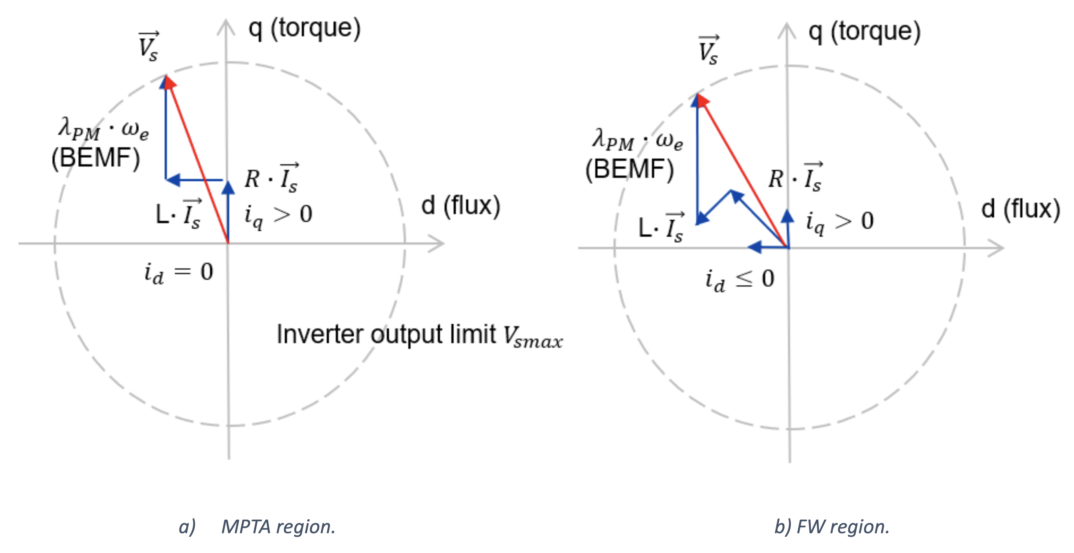
Fig. 11: Electric machine phasor diagram.
Although maximizing the torque ensures higher efficiencies, there are physical limitations and if the motor speed exceeds the base speed, the motor cannot operate in MPTA as there will be not enough dc-link voltage available to overcome the motor BEMF.
The solution for this can be found in the torque equation shown in Eq. 4. The d-axis linkage flux has two components one of which is due to the permanent magnet field. The sign convention is such that for negative Id currents, the second term subtracts from the PM flux which holds true for motoring operation as Iq ≥ 0 and Id ≤ 0.

(Eq. 4)
For the algorithm to ensure MTPA, it will set the reference d-axis current to zero. The reason being it should not counteract the PM flux. On the other hand, if the machine has exceeded the base speed, see Fig. 11-b, then a proper value for the pair (Iq , Id) must be picked to ensure partial concealment of the PM flux term, thus overcoming the inverter limitation. This operation mode is known as Field Weakening (FW).
The definition for the base speed is expressed in Eq. 5, where the term Vs_max represents the maximum inverter output voltage (dependent on the modulation scheme) and the term Is_max representing the maximum inverter current or nominal motor current (whichever is the smallest).
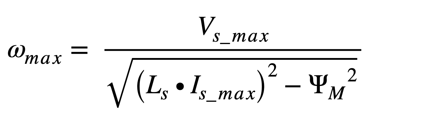
(Eq. 5)
Single-shunt current measurement:
The single-shunt current measurement is a very popular approach amid the applications from tens of watts up to a couple thousands of watts where the sensorless operation is required. It offers an attractive reduction to the Bill of Materials cost. Another advantage of this method is that there are no concerns with regards to the matching of the ADC signal paths (2- or 3-phase current sensing), because all currents will be sampled using the same ADC channel. The need for measuring the current with the SVM will be explained in the next section.
Fig. 12 shows an example of SVM modulation with center aligned PWM for the transition between vector V5 “011” to V4 “001”. Within this sector, the phase currents u and v are negative while w is positive. Each inverter leg will only carry current if the respective LS switch is turned on, i.e., for the complementary of the PWM period (1-D). Therefore, the summation of the three individual inverter leg currents equals to the single-shunt signal. Of course, there is no signal if either the “000” or “111” null vectors are applied.
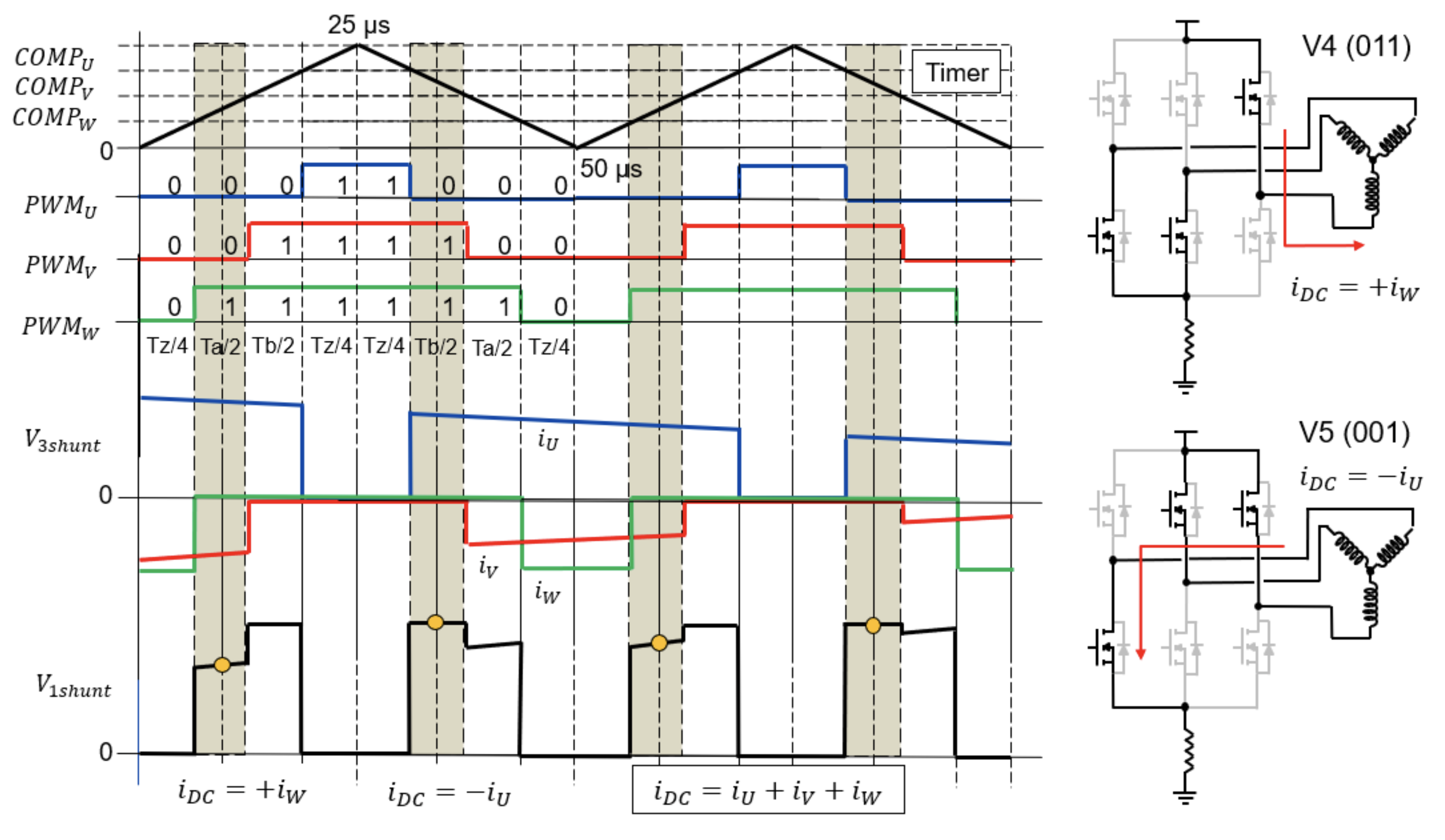
Fig. 12: SVM with Center Aligned PWM and single-shunt current signal represented for the sector 5 to 0
Position Observer:
As the application power raises, so does the performance requirements for it. It is therefore difficult to meet the criteria using an ordinary Six-Step modulation. Instead, the designers must opt for the SVM modulation. In addition, these applications often require sensorless operation due to cost constraints. But, because in the SVM approach there are no floating phases, it is not possible anymore to do direct BEMF sensing to determine the exact ZC instants.
In this sense, many rotor position estimator algorithms appeared in the literature (and in the industry) to allow sensorless operation of machines while using the SVM modulation. To execute such kind of algorithms, the software needs to know the dynamic stator voltages and currents, among other electrical quantities. Thus, the importance of the previous section about shunt current sensing.
Among the various estimation methods available in the literature, the voltage model is the most famous one (some authors call it flux estimator). It is based on the stator voltage equations. Through the stator voltage equations one can obtain the rotor flux from which the rotor angular position is determined. Although simple this algorithm can provide good results if the motor parameters are well known, and the machine current and voltage measurements exhibit small errors.
At low speeds and start-up condition the traditional sensorless schemes tend to suffer. Because the equations are dependent on the flux, and the BEMF is too small at this point, the measurement errors contribute to lower the Signal-to-Noise ratio (SNR). To address this inability, many amendments or enhancements were proposed to create hybrid estimators, one suited for low speeds and another one for the high speeds, and even different types of estimators.
Stepper Motors
A subset of BLDC motors, stepper motors divide a full rotation into incremental steps. Two-phase bipolar stepper motors, consisting of coils connected to an H-bridge, provide accurate positioning. Stepper motors offer step modes, including full-step, half-step, scaled half-step, and micro-step, each influencing torque, accuracy, and movement.
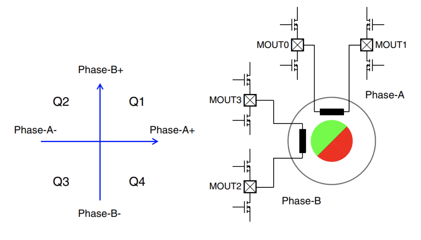
Fig. 6: Bipolar stepper motor circuit
Step Modes: Exploring full-step, half-step, scaled half-step, and micro-step modes
Stepper motors operate in different step modes, determined by the number of pulse commands from the controller.
In full-step mode, both motor phases are energized, allowing four steps per electrical revolution.
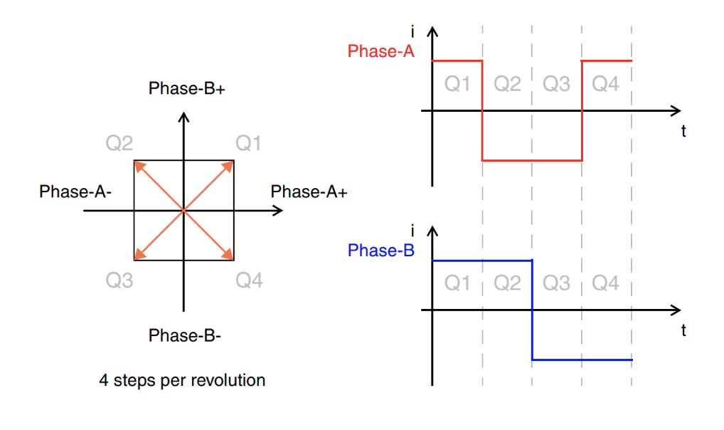
Fig. 7: Full step mode
Half-step mode inserts an intermediate step between full-steps, offering eight steps per revolution.
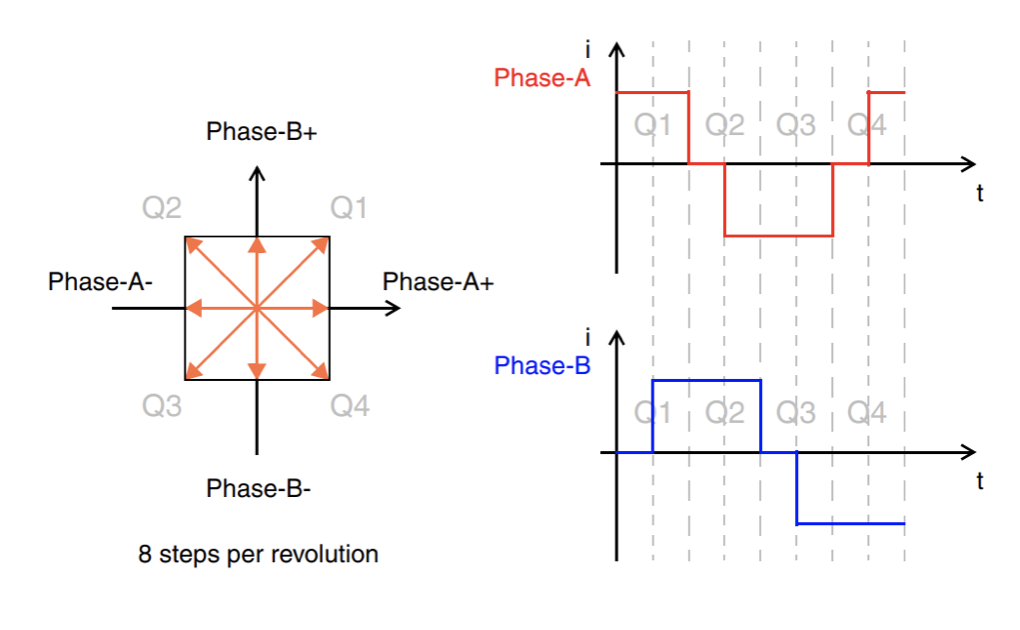
Fig. 8: Half-step mode
Scaled half-step mode adjusts current vectors during intermediate steps to minimize torque ripple.
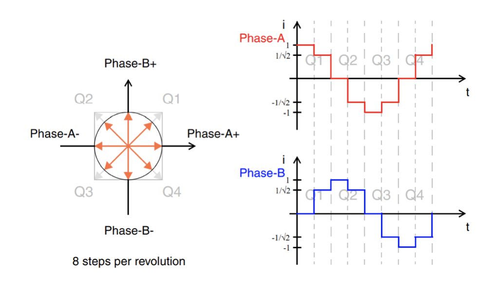
Fig. 9: Scaled half-step mode
Micro-step mode employs sine/cosine-shaped currents, allowing for versatile vector formations with resolutions defined per full-step or quadrant, typically with up to 32 micro-steps per quadrant. The micro-step resolution is determined by a sine table in the application software, enabling precise control with various step widths.
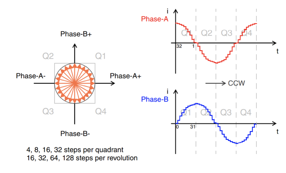
Fig. 10: Micro-step mode
Current Decay: Managing current decay for optimal performance in micro-stepping
To achieve a sine-shaped current waveform for micro-stepping across the motor's entire speed range, effective current decay control is essential. The goal is to minimize current ripple for reduced emissions and lower acoustic noise. The approach involves adapting the current decay strategy based on motor speed and current levels.
In low-speed and low-current scenarios, asynchronous slow decay is the preferred mode. When a switch in the H-bridge is turned off, the freewheeling current flows through the intrinsic diode of the opposing switch in the same leg. This decay mode is particularly effective for rising or falling current at low speeds and low current levels.
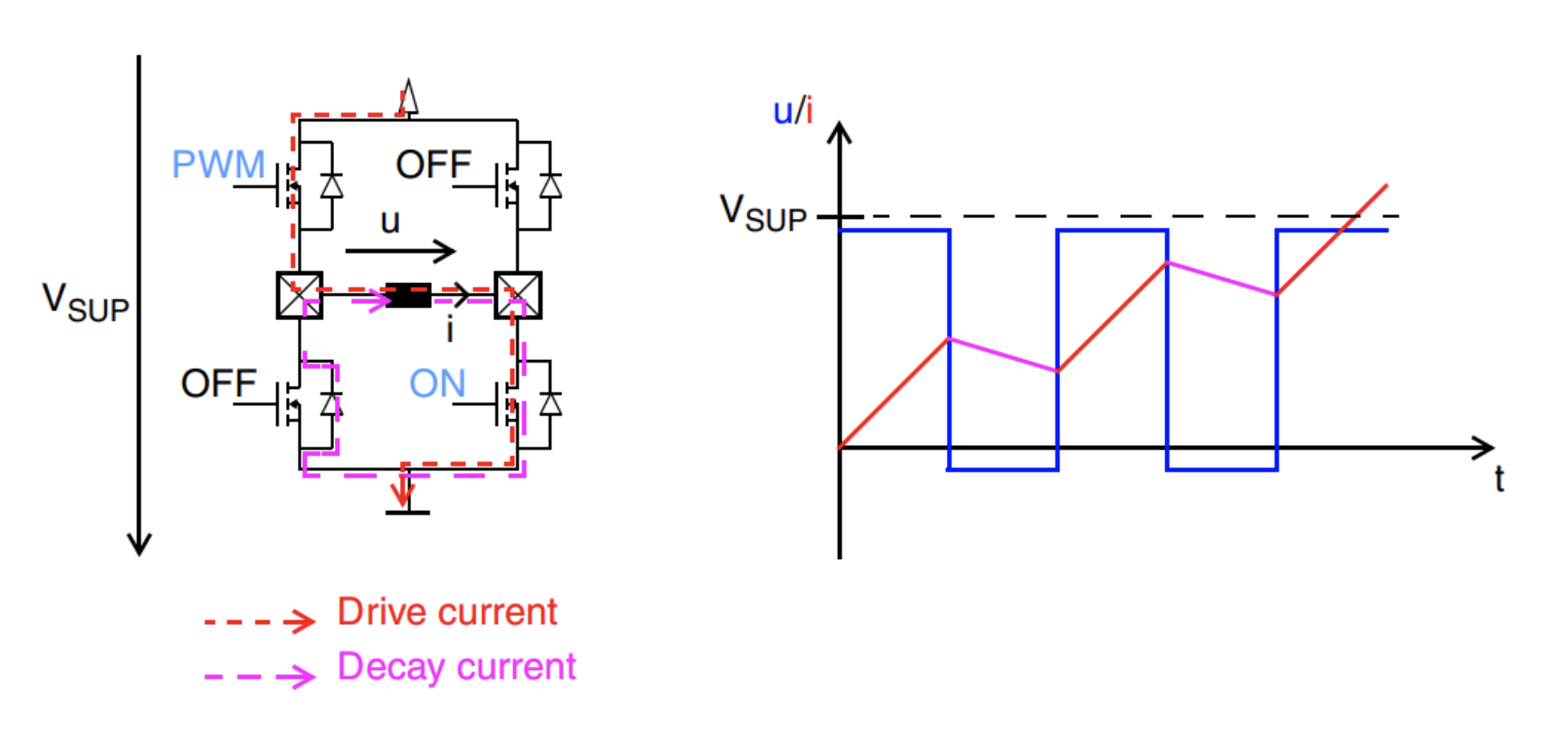
Fig. 12: Asynchronous Slow Decay
For high-speed and high-current situations, synchronous fast decay is the optimal mode. In this mode, both current-conducting switches in the H-bridge are turned off simultaneously, and the opposing switches in the corresponding legs are turned on. The freewheeling current flows through the activated switches back into the supply. This decay mode is well-suited for scenarios involving falling current at high speeds and high current levels.
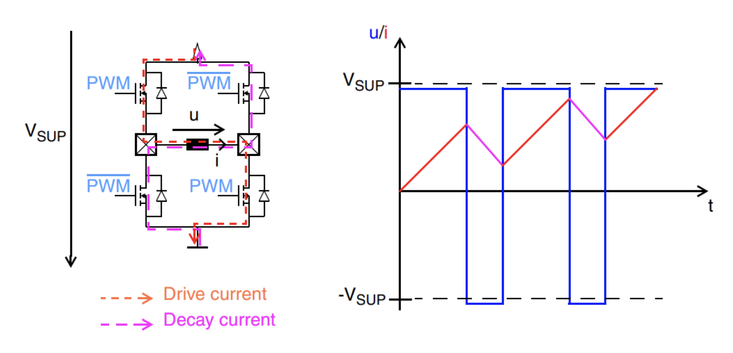
Fig. 13: Synchronous fast decay
In scenarios where motor speed and current levels vary, mixed decay, a combination of fast and slow decay, proves effective. This approach involves applying fast synchronous decay first, followed by asynchronous slow decay within one PWM cycle. The ratio of fast-to-slow decay can be adapted to the current level and motor speed. Mixed decay is the preferred mode for decreasing current at mid to high speeds and high to low current levels.
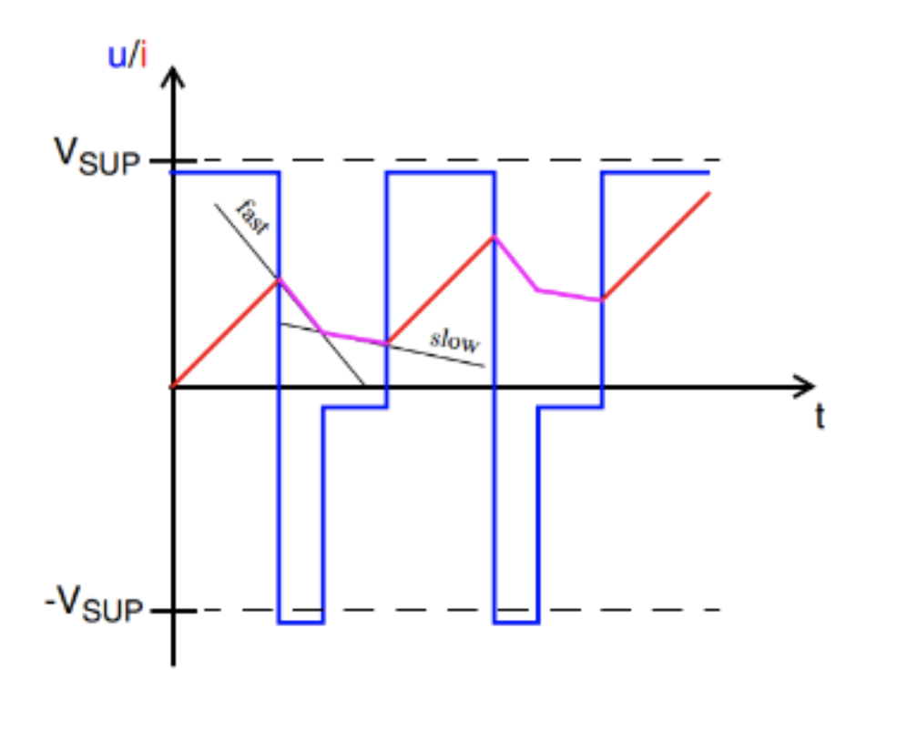
Fig 14: Mixed decay
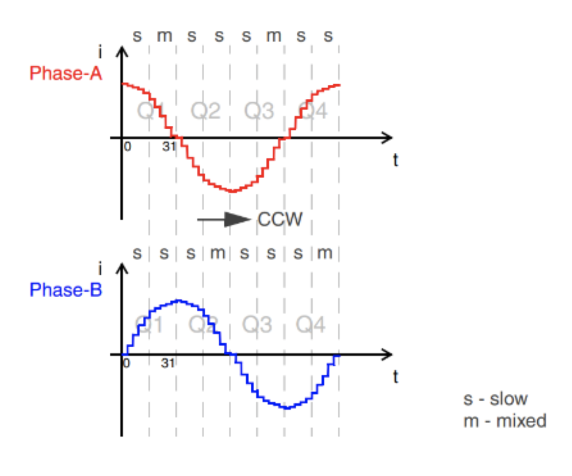
Fig. 15: Example of slow and mixed decay usage in micro-step mode
By implementing a fixed ratio between fast and slow decay in the application software, optimal performance is ensured. Additionally, a carefully defined current threshold prevents motor reversal during low current levels, with slow decay applied when the set current level falls below this threshold.
Stall Detection: Monitoring BEMF voltage for stall detection and step loss prevention
Stall detection is achieved through BEMF voltage measurement, particularly in micro-step mode. In this mode, the BEMF voltage is proportional to motor speed, allowing for straightforward identification of whether the motor is in motion. However, due to the measurement occurring only when one phase is not energized, the view of the BEMF voltage is limited. In an ideal scenario without load and losses, the BEMF voltage peak aligns with the point of zero phase current. In real-world conditions with applied load, the rotor lags behind the stator field, introducing a load-dependent phase lag. This lag results in a shift in the BEMF voltage from the peak, indicating zero torque, to the zero-crossing point, indicating stall torque. This shift signifies the point of stall and step loss.
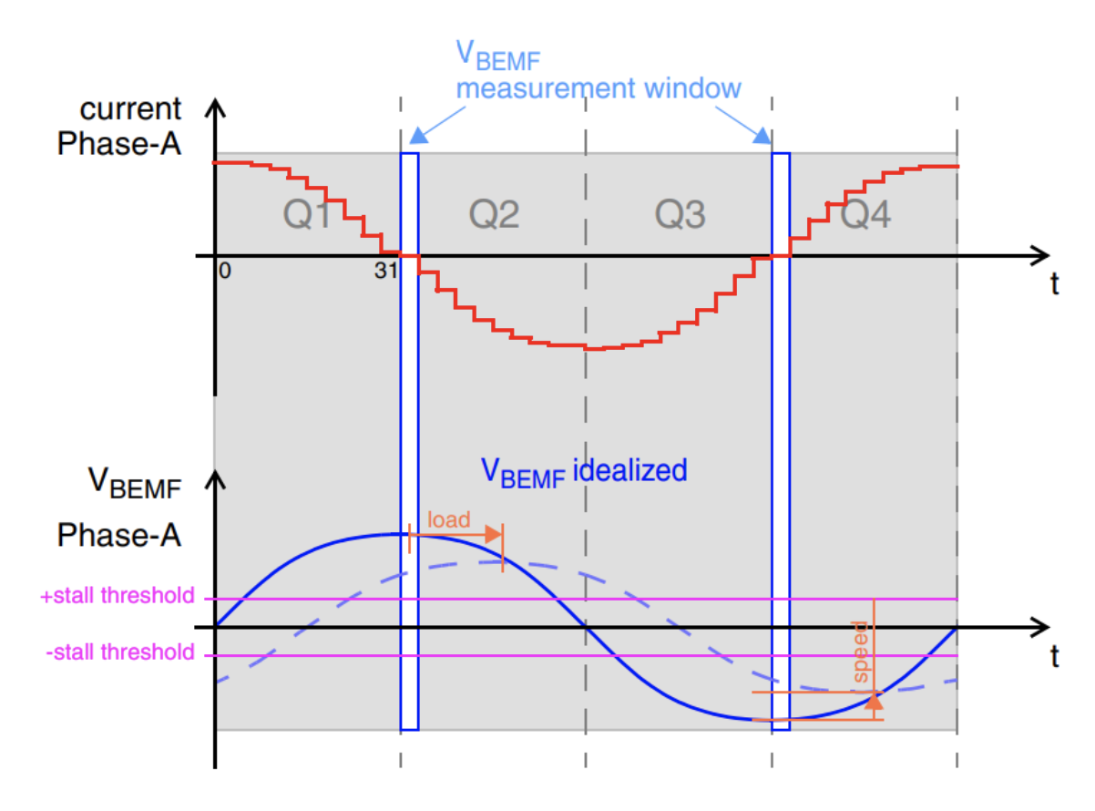
Fig. 17: VBEMF measurement for stall detection
Conclusion
Efficient DC motor control is vital for diverse applications. Understanding the nuances of BDC, BLDC, and stepper motors, along with advanced control techniques, ensures optimal performance and longevity. Embedded systems, exemplified by Micronas' HVC 5x family, offer sophisticated solutions for precise and reliable motor control.